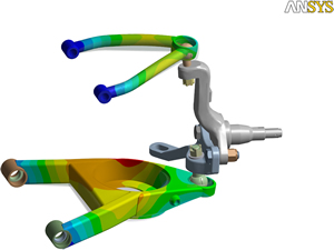
More and more engineers in Australian and New Zealand companies are performing computer simulations as part of their design process. These simulations are aimed at determining how their product designs will perform in the real world. The most commonly used form of simulation for mechanical engineers is a structural and/or thermal finite element analysis (FEA). FEA software is also one of the most mature technologies in the area of simulation.

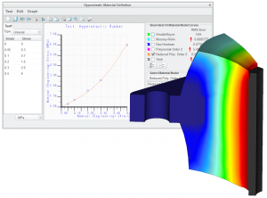
ANSYS offers a full complement of structural elements, material models and analyses targeted toward understanding and solving complex structural phenomena. A comprehensive library of linear and nonlinear material models can handle composites, plasticity, hyperelelasticity, viscoelasticity, creep and special materials including cast iron and shape memory alloys. A complete set of elements are specially architected for finite strain, large deformations and large rotations. Contact is easily accounted for, including friction and sliding, with automatic contact detection for imported assemblies. Several advanced contact solution features are also supported for one and two dimensional surfaces on either flexible or rigid bodies.
The software offers a variety of analysis types such as static, modal, harmonic, random vibration, rotordynamics, and nonlinear implicit and explicit dynamics. It is also possible to perform a sequential combination of these analyses, for example a pre-stressed modal analysis. In short, this is a total structural package which also enlists high performance computing capabilities, such as parallel processing, to produce highly scalable results and make a 100M dof problem attainable. Lastly, if by chance we have not anticipated and provided for your structural analysis needs, we have provided documented interfaces to allow you to customize the solver and create your own elements, materials, and loads – or script your own solution procedures.
PTC Creo Simulate is a structural, thermal and vibration analysis solution with a comprehensive set of finite elements analysis (FEA) capabilities that allow you to analyze and validate the performance of your 3D virtual prototypes before you make the first part.
Start by modeling your design in PTC Creo Parametric, click a single tab on the user interface, and then apply loads, materials, and boundary conditions to the design geometry in PTC Creo Simulate. It’s easy. Even better, you can see the results quickly. If needed, adjust the model to produce higher quality designs faster.


